
Length Measurement Accuracy of the Enpose Tracking System
Evaluation of a two-sensor configuration following VDI/VDE 2634 Part 1
Version 1.1 · October 15, 2026 · Dr. Konstantin Schauwecker, Enpose
Measurements performed on October 9, 2026 in Leinfelden-Echterdingen, Germany
1 Summary
| Quantity | Result |
|---|---|
| Maximum length measurement error | 0.87 mm |
| Limit of the length measurement error | E = 0.58 mm + 0.18 mm/m · L |
| Longest test length | 2440 mm |
| Basis | 323 test lengths on 7 measuring lines, from 72 recordings |
| Quantity | Result |
|---|---|
| RMS length error | 0.33 mm |
| Median / 95th percentile of the absolute length error | 0.24 mm / 0.62 mm |
| Lengths up to 600 mm, measured without repositioning the artifact | maximum 0.49 mm, RMS 0.21 mm |
| Temporal noise of a static marker (3D standard deviation) | median 0.025 mm |
| Change of the measured orientation over a 600 mm translation | median 0.24°, RMS 0.38°, maximum 0.86° |
2 Introduction and Scope
The purpose of this report is to document the length measurement accuracy of the Enpose tracking system (hereafter: the system) in one defined setup, using an established and comparable method.
VDI/VDE 2634 Part 1 [1] is a guideline for the acceptance testing of optical 3D measuring systems with point-by-point probing. We chose it for two reasons. It is widely used for optical measuring systems, so the results can be compared with those of other systems. And its quality parameter, the length measurement error, is easy to interpret: it states by how much a measured distance between two points can deviate from the true distance, anywhere in the measuring volume. The definition is similar to the one that ISO 10360-2 [2] uses for coordinate measuring machines.
The tested system consisted of two sensors. The system can also localize a marker with a single sensor, but at reduced accuracy. Two sensors are therefore the smallest configuration intended for accurate measurement, and the results show what is achievable with it. Additional sensors add observations of the marker and improve the measurement geometry, so better results are expected with more hardware. Configurations with more sensors are the scope of future reports.
The results apply to the sensor arrangement and the measuring volume described in this report. Other arrangements or volumes need their own evaluation. This report is product information. It is not an acceptance test or a certification of any installation, and the evaluation deviates from the guideline in several points, which are listed and explained in section 6.
3 System Under Test
The system localizes a marker in six degrees of freedom, that is, in position and orientation. The marker carries active infrared emitters, which are observed by camera-based sensors. All processing happens inside the sensors, so no external computer is needed for tracking. Poses are delivered at a rate of 66.6 Hz with minimal latency. Further details are available on the product website [4].
The following configuration was tested:
| Item | Value |
|---|---|
| Sensors | Serial numbers S001 and S002 |
| Marker | Serial number M001 |
| Firmware version | 26.10.09 |
| Distance between the sensors | approx. 2.5 m |
| Angle between the viewing directions | approx. 45° |
| Mounting height of the sensors | approx. 1500 mm above the floor |
| Downward tilt of the sensors | approx. 25° |
| Distance of the marker from each sensor during the test | 1.3 to 4.2 m |
The two sensors were calibrated against each other directly before the measurement. For this, a calibration marker of 380 mm length was moved through the entire measuring volume. The calibration residual, the RMS angular deviation between the observed and the predicted directions of the calibration marker’s emitters, was 0.053 mrad. The system can also recalibrate itself automatically during operation. This function was disabled, so the calibration remained unchanged for the whole measurement.
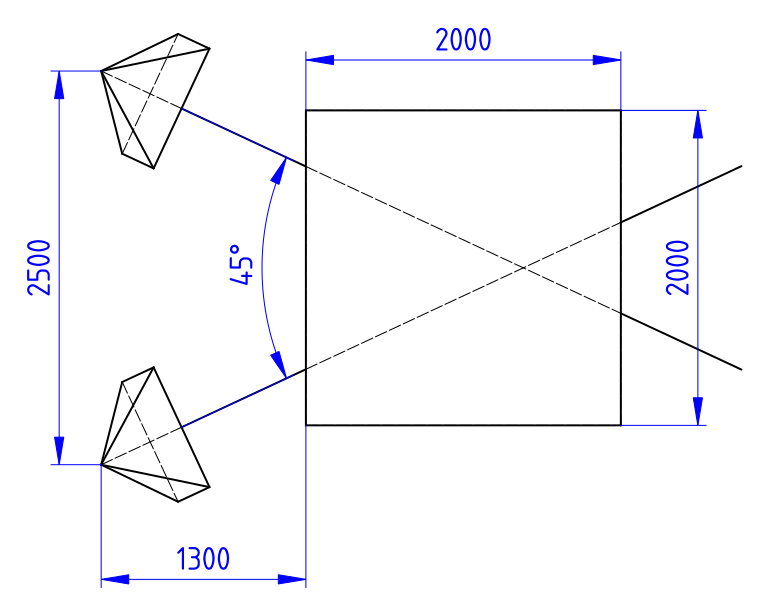
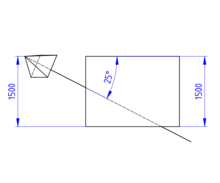
Figure 1: Sketch of setup with both sensors and the measuring volume seen from (a) the top and (b) the side.
4 Methodology
4.1 Method of the Guideline
The guideline [1] tests a measuring system with an artifact that provides known distances between probing points. The artifact is measured at several places in the measuring volume. For each test length, the length measurement error is the difference between the length measured by the system and the reference length of the artifact:
Δl = measured length − reference length
The quality parameter E is the limit that no length measurement error exceeds. Because errors of optical systems typically grow with the measured length, E is stated as a length-dependent expression E = A + K · L, with a constant part A and a part K · L that is proportional to the length L.
To make sure that the result holds for the whole measuring volume, the guideline requires seven measuring lines with at least five test lengths each. The longest test length of every line must be at least as long as the shortest side of the volume, and the longest test length overall should be at least two-thirds of the body diagonal. The lines are arranged so that they reach all corners of the volume.
4.2 Measurement Artifact
The artifact is an extruded aluminum profile with three stops, which are spaced about 300 mm apart. The marker is slid against a stop and held in place by a spring. The spring gives a repeatable contact force, so the marker comes to rest at the same place each time. Moving the marker from one stop to another displaces the marker by a known distance, without changing its orientation.
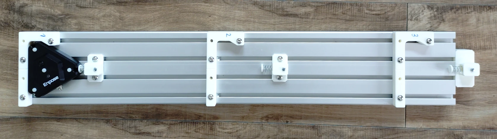
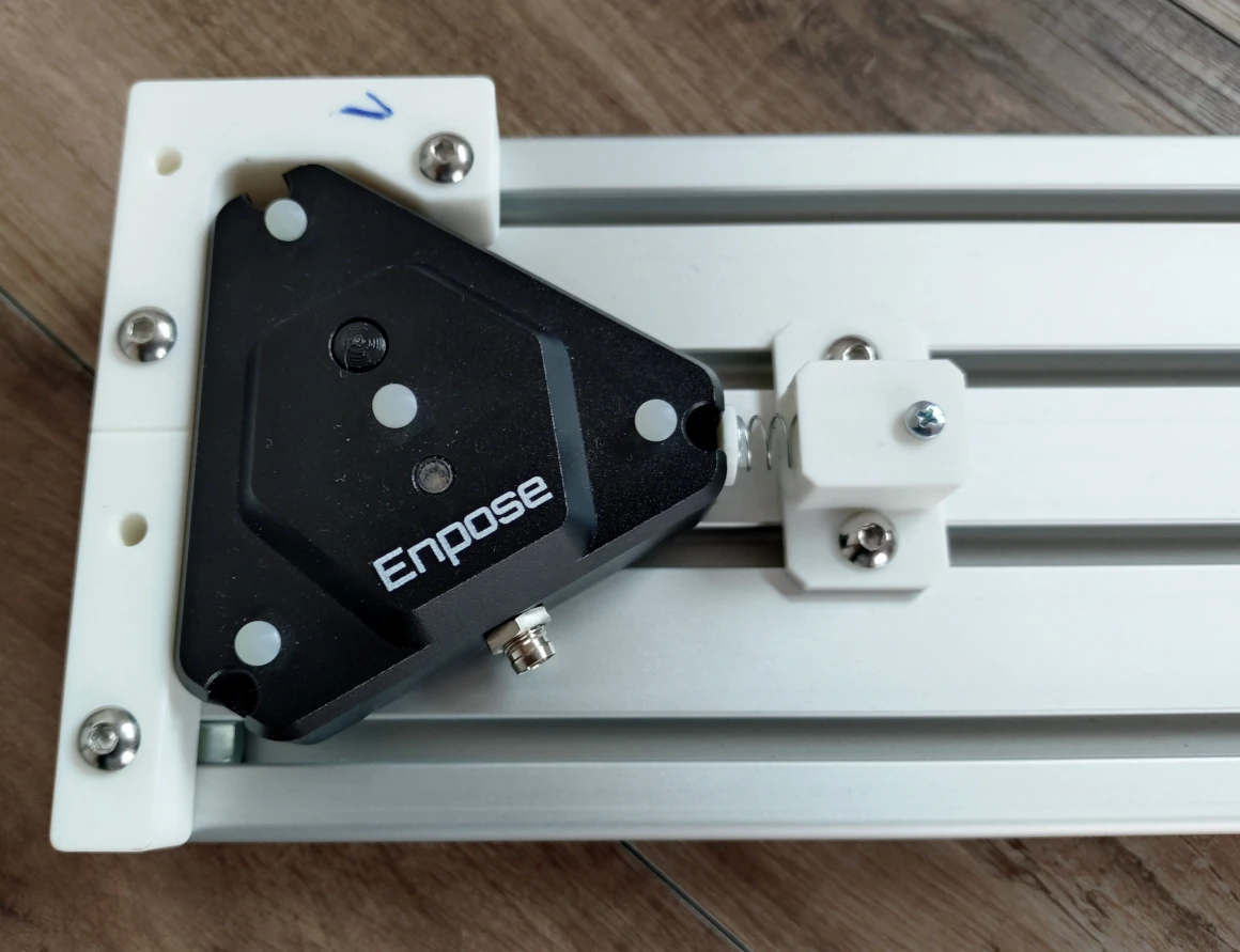
Figure 2: Photo of (a) the full measurement artifact and (b) close-up of spring mechanism.
The stop distances were determined in-house on October 8, 2026, the day before the measurement. An outside micrometer was first set against a 325 mm setting standard. The outer distance across two neighboring stops was then measured repeatedly, corrected for the room temperature, and reduced by the measured width of the stop. This gives the following distances:
| Distance | Value |
|---|---|
| Stop 1 to stop 2 | 300.14 mm |
| Stop 2 to stop 3 | 299.79 mm |
| Stop 1 to stop 3 | 599.94 mm |
The standard uncertainty is estimated at 0.04 mm for the distance from stop 1 to stop 2, at 0.03 mm for the distance from stop 2 to stop 3, and at 0.06 mm for the distance from stop 1 to stop 3. The estimate combines the scatter of the repeated micrometer readings, the accuracy of the micrometer and the thermal expansion of the aluminum profile between the measurement of the artifact (22.2 °C) and the test (about 20 °C, taken as 19 °C for this estimate). The artifact has no calibration certificate; section 6 discusses what this means for the results.
4.3 Measuring Volume and Measuring Lines
The measuring volume is 2000 × 2000 × 1500 mm (length × width × height). The guideline recommends this size for acceptance testing, while permitting others [1]. We chose the recommended volume so that the results can be compared directly with those of other systems tested in accordance with the guideline. The system itself is not limited to this volume.
Seven measuring lines were used. Three run along edges of the volume and four along face diagonals. Four lines lie at floor level, where the artifact rests on the floor. For the other three, the artifact was clamped onto a rail.
| Line | Course | Artifact mounting |
|---|---|---|
| 1 | Long edge at floor level | On the floor, tilted upwards by 45° |
| 2 | Diagonal of the floor face | Flat on the floor |
| 3 | Second diagonal of the floor face | Flat on the floor |
| 4 | Long edge at floor level, opposite to line 1 | Flat on the floor |
| 5 | Diagonal of a side face | Clamped on a diagonal rail |
| 6 | Diagonal of the opposite side face | Clamped on a diagonal rail |
| 7 | Long edge at the top of the volume | Clamped on a horizontal rail, tilted 10° against the vertical |
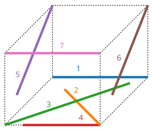
Figure 3: 3D view of the measuring volume with the seven measuring lines, seen from the front.
Figure 3 is a schematic overview. It shows the measuring volume from the front, which is the side where the sensors are located. Figure 4 shows the positions that were actually recorded, in three projections of the measuring volume.
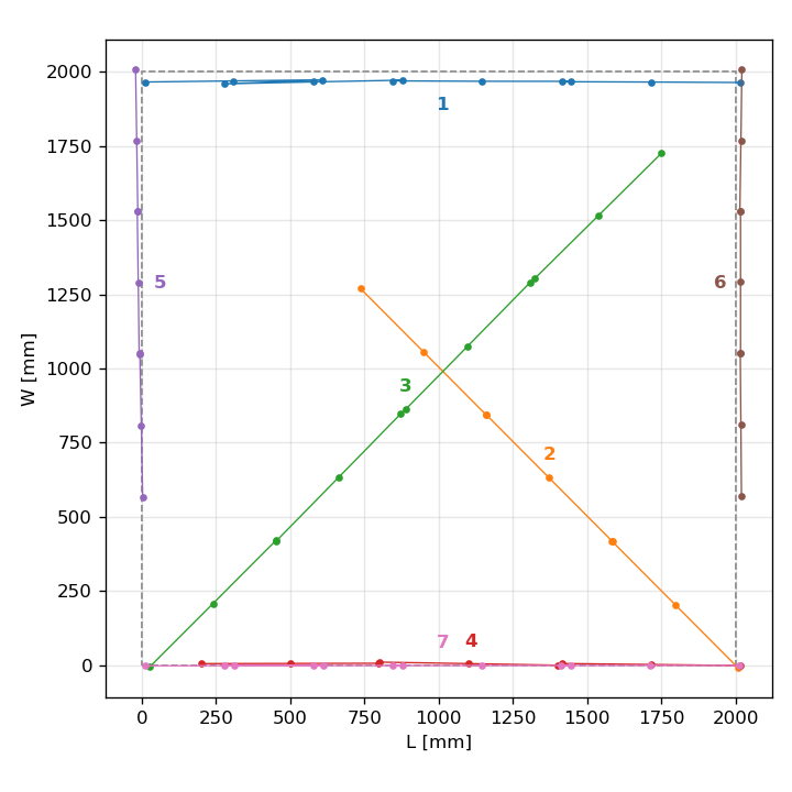
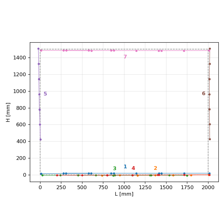
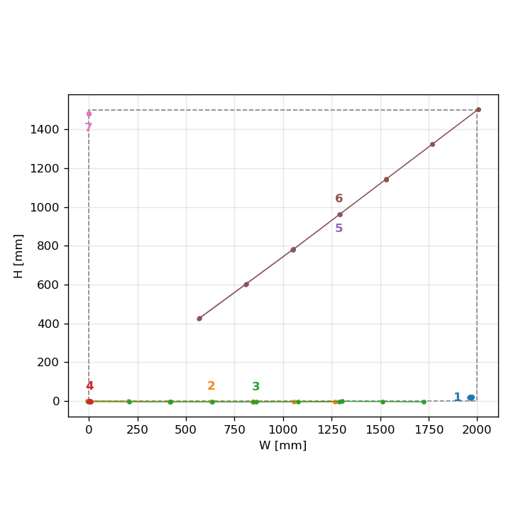
Figure 4: Recorded positions on the seven measuring lines in (a) top, (b) front and (c) side view. Dashed: nominal volume.
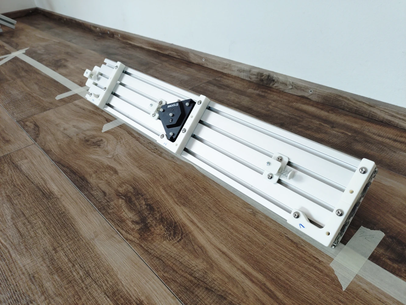
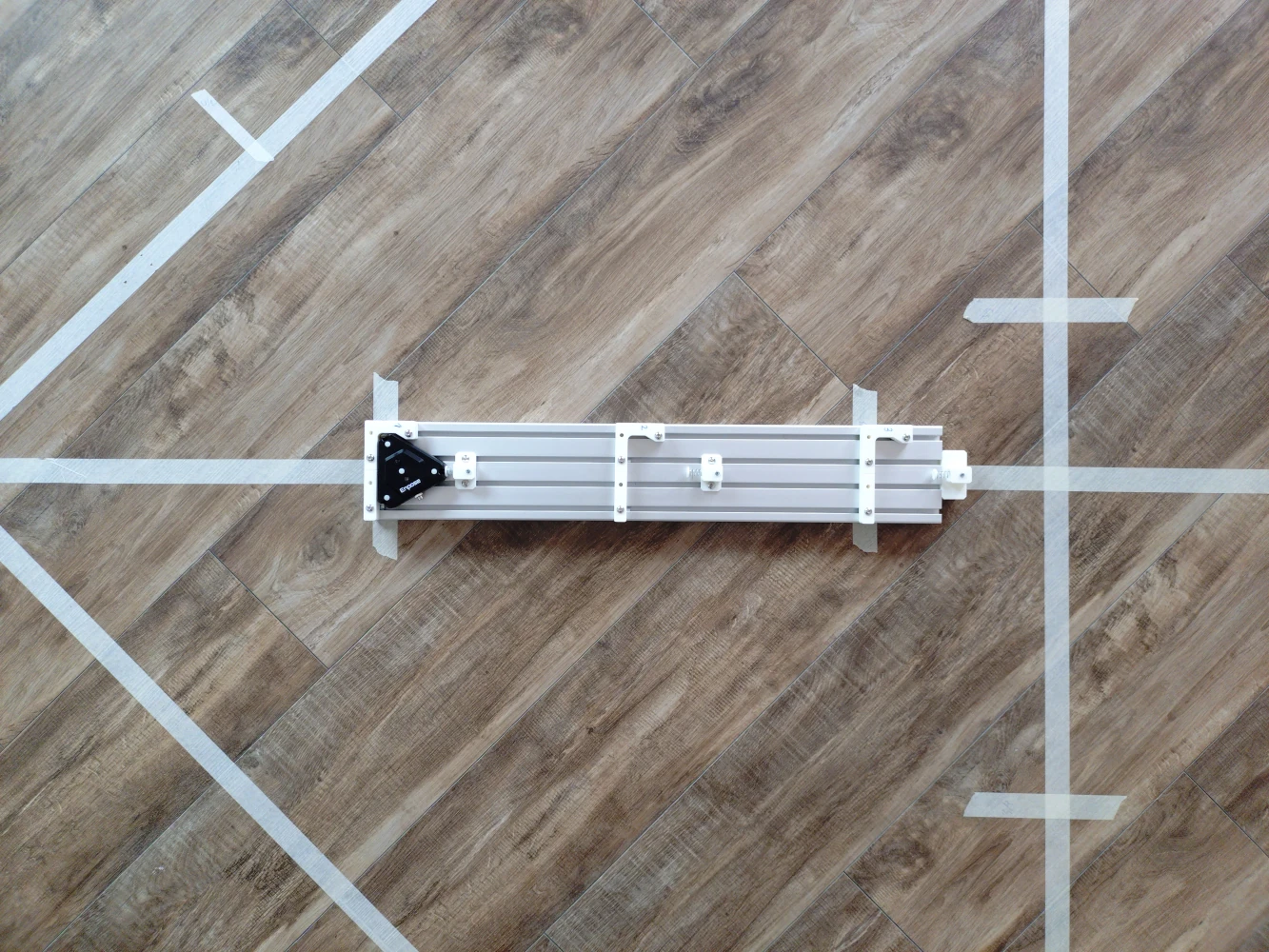
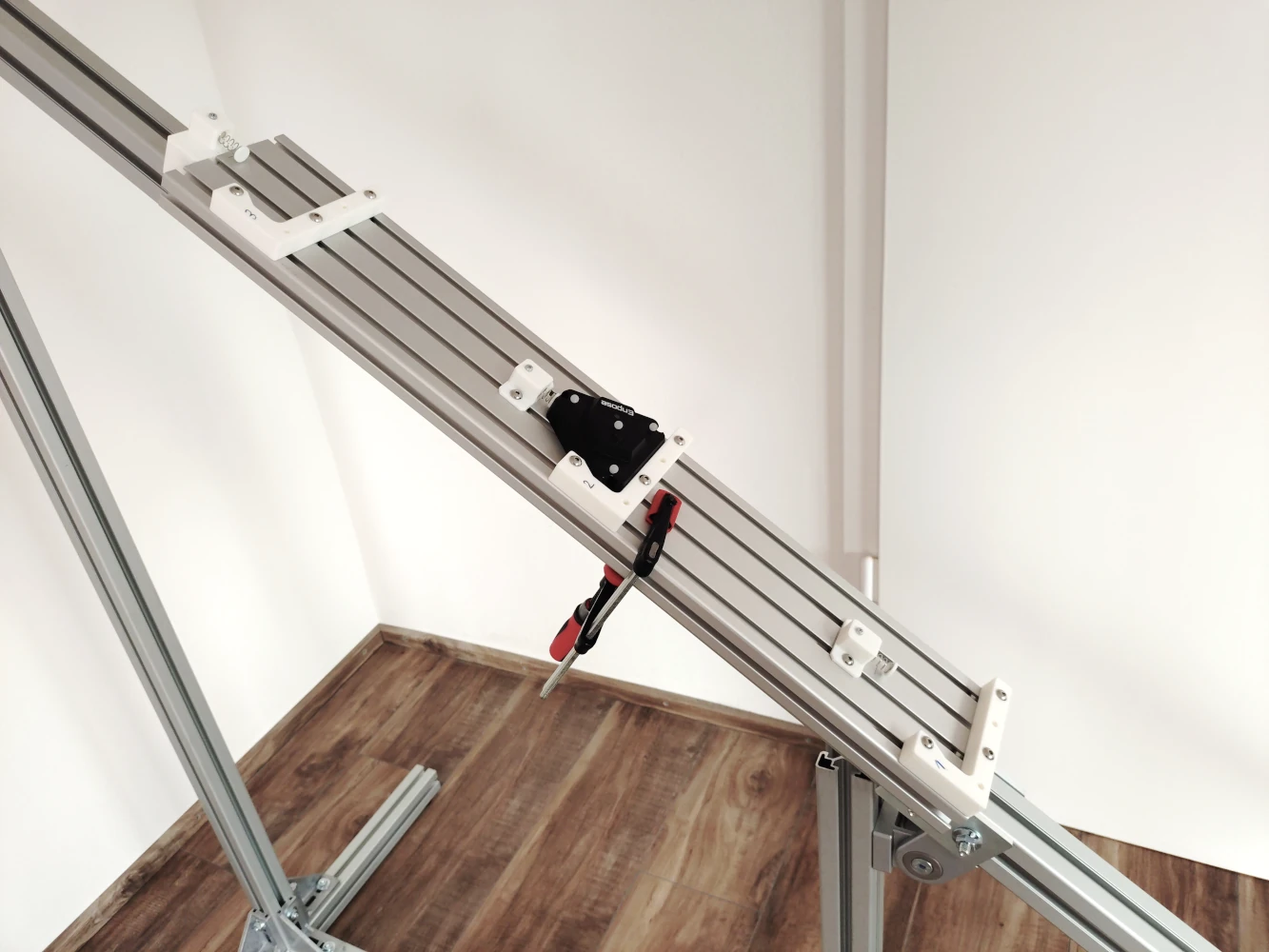
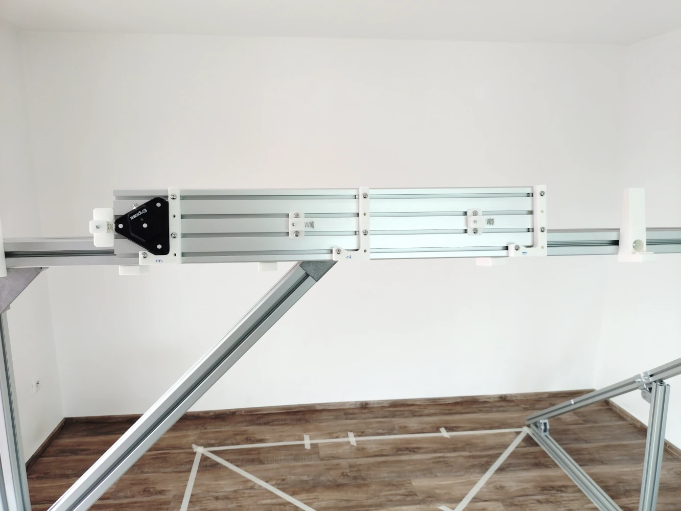
Figure 5: Photos of the artifact (a) tilted on the floor, (b) flat on the floor, (c) on diagonal rail, and (d) on horizontal rail.
The mounting of the artifact differs between the lines, so the marker was observed in several orientations relative to the sensors.
With this arrangement, the requirements of the guideline on the measuring lines are met:
| Requirement of the guideline | Required | Achieved |
|---|---|---|
| Measuring lines | 7 | 7 |
| Test lengths per line | ≥ 5 | 34 to 63 |
| Longest test length per line | ≥ 1500 mm | 1798 to 2440 mm |
| Longest test length overall | ≥ 2134 mm | 2440 mm |
| Volume corners reached | 8 | 8 (within 45 mm) |
4.4 Linking of Artifact Positions
The artifact is 600 mm long, while the guideline requires test lengths above 1500 mm. Where no artifact of sufficient length is available, the guideline allows a long test length to be represented by overlapping artifacts. We apply this principle with a single artifact that is moved along the measuring line. Each new position is chosen so that one of its stops lies close to a stop of the previous position.
Two such neighboring stops form a link. The gap that remains between them is small and is measured by the system itself. The reference length of a linked test length is then composed of the known stop distances, the measured link gaps and the measured direction of the artifact in each position. Because the system only has to bridge a short gap, the link contributes little uncertainty: at most 0.03 mm for any test length (expanded uncertainty with coverage factor k = 2, as defined in [3]), which is small against the measured errors.
How far the artifact was moved between positions depends on the line:
- Lines 2 to 6 use three or four positions end to end. The artifact was moved by about its full length (approx. 600 mm), so that stop 1 of the new position lies at stop 3 of the previous one. The remaining gaps were between 1 and 20 mm. Three positions give a longest test length of about 1800 mm, which exceeds the required 1500 mm. Line 3 uses four positions and provides the longest test length of 2440 mm.
- Lines 1 and 7 have to reach a corner of the volume at both ends, because eight corners must be covered with seven lines. They run along a 2000 mm edge, which is not a multiple of the artifact length: three positions end to end reach only 1800 mm, and a fourth would extend beyond the volume. The artifact was therefore moved by shorter steps, twice by about 570 mm and once by about 270 mm. With the last step, two stops of the new position lie next to two stops of the previous one. The gaps on these lines were between 30 and 34 mm.
In all cases the gap stayed below 40 mm. Test lengths within one artifact position (direct lengths) do not depend on any link. They are reported separately in section 5.2.
4.5 Recording Procedure
The artifact was placed at three or four consecutive positions along each line, as described above. At each position the marker was recorded at each of the three stops, which gives 72 recordings in total.
Each recording lasts one second and contains about 67 poses, which are averaged to one position. This averaging is the declared operating mode of the test. It is appropriate for static measurements, where the marker rests while a point is taken. Only poses observed by both sensors with all four emitters were used. An outlier filter was applied to the poses of each recording, but it rejected none. The marker orientation was kept constant within a line.
The system had been running for several hours before the measurement, so it had reached its operating temperature. The room temperature was about 20 °C, and the room was lit by a combination of natural and artificial light.
4.6 Evaluation
All pairs of recorded points on a line that are connected through links form a test length. This gives 323 test lengths, of which 72 are direct and 251 are linked. The test lengths of a line are not independent of each other, since they are formed from the same 12 or 9 recorded points.
The limit E is the tightest expression A + K · L that encloses all length measurement errors. A and K were rounded up to two decimals. E is thus determined from the errors measured in this test. It describes the result of this test and is not a guaranteed specification of the system.
The supplementary metrics are computed as follows:
- RMS, median and 95th percentile are taken over the absolute errors of all 323 test lengths.
- Temporal noise is the 3D standard deviation of the positions within one recording, before averaging.
- The orientation change is the rotation angle between the orientations measured at stop 1 and stop 3 of one artifact position. These two stops give the largest translation without a change in orientation, about 600 mm.
5 Results
5.1 Length Measurement Error
The maximum length measurement error over all 323 test lengths is 0.87 mm. All errors lie within the limit
E = 0.58 mm + 0.18 mm/m · L
The largest error occurred at a test length of 1818 mm. For the longest test length of 2440 mm, the error was 0.40 mm.
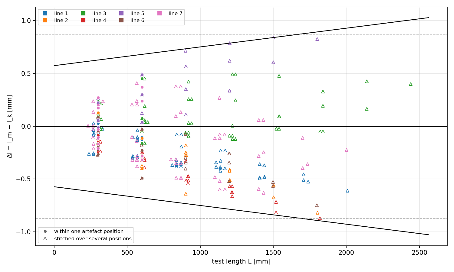
Figure 6: Error diagram, Δl over test length for all test lengths with the limit E. Dashed: max(|Δl|) = 0.87 mm.
| Line | Test lengths | Longest length [mm] | Maximum error [mm] | RMS error [mm] |
|---|---|---|---|---|
| 1 | 62 | 2007 | 0.61 | 0.30 |
| 2 | 34 | 1802 | 0.82 | 0.35 |
| 3 | 63 | 2440 | 0.49 | 0.20 |
| 4 | 34 | 1818 | 0.87 | 0.43 |
| 5 | 34 | 1801 | 0.84 | 0.43 |
| 6 | 34 | 1798 | 0.75 | 0.31 |
| 7 | 62 | 2000 | 0.63 | 0.30 |
| All | 323 | 2440 | 0.87 | 0.33 |
5.2 Supplementary Results
The following results are not defined by the guideline. They answer questions that the maximum error alone does not.
What error is typical? The maximum error describes the worst of 323 test lengths. The RMS error over all test lengths is 0.33 mm and the median absolute error is 0.24 mm. 95 % of the test lengths have an error below 0.62 mm.
How accurate are shorter distances? The 72 direct lengths of 300 and 600 mm were measured without moving the artifact and involve no link. Their maximum error is 0.49 mm and their RMS error is 0.21 mm. For the 251 linked lengths, the maximum error is 0.87 mm and the RMS error is 0.35 mm.
How stable is a static measurement? The temporal noise of the marker position within a one-second recording has a median of 0.025 mm over the 72 recordings, with a maximum of 0.26 mm. This is the scatter to expect from a single pose without averaging. It is small compared with the length measurement errors, which shows that the averaging over one second has little influence on the results above.
How consistent is the measured orientation? When the marker is translated by about 600 mm without rotating, the measured orientation changes by a median of 0.24° and an RMS of 0.38° over the 24 artifact positions, with a maximum of 0.86°. The changes are larger on lines 1 and 3 (RMS 0.60° and 0.61°) than on the other lines (RMS 0.18°). An orientation error that is the same at both stops does not appear in this value, so it is not a measure of absolute orientation accuracy.
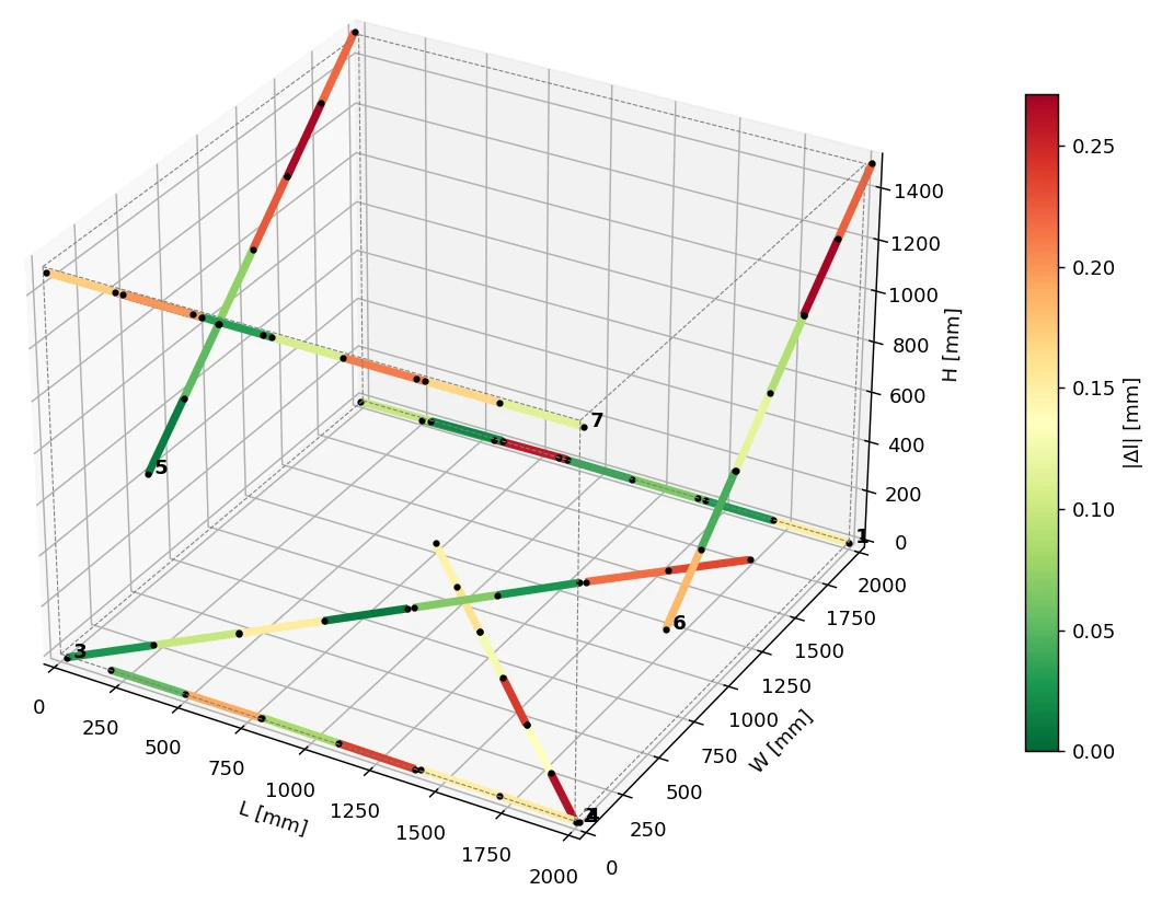
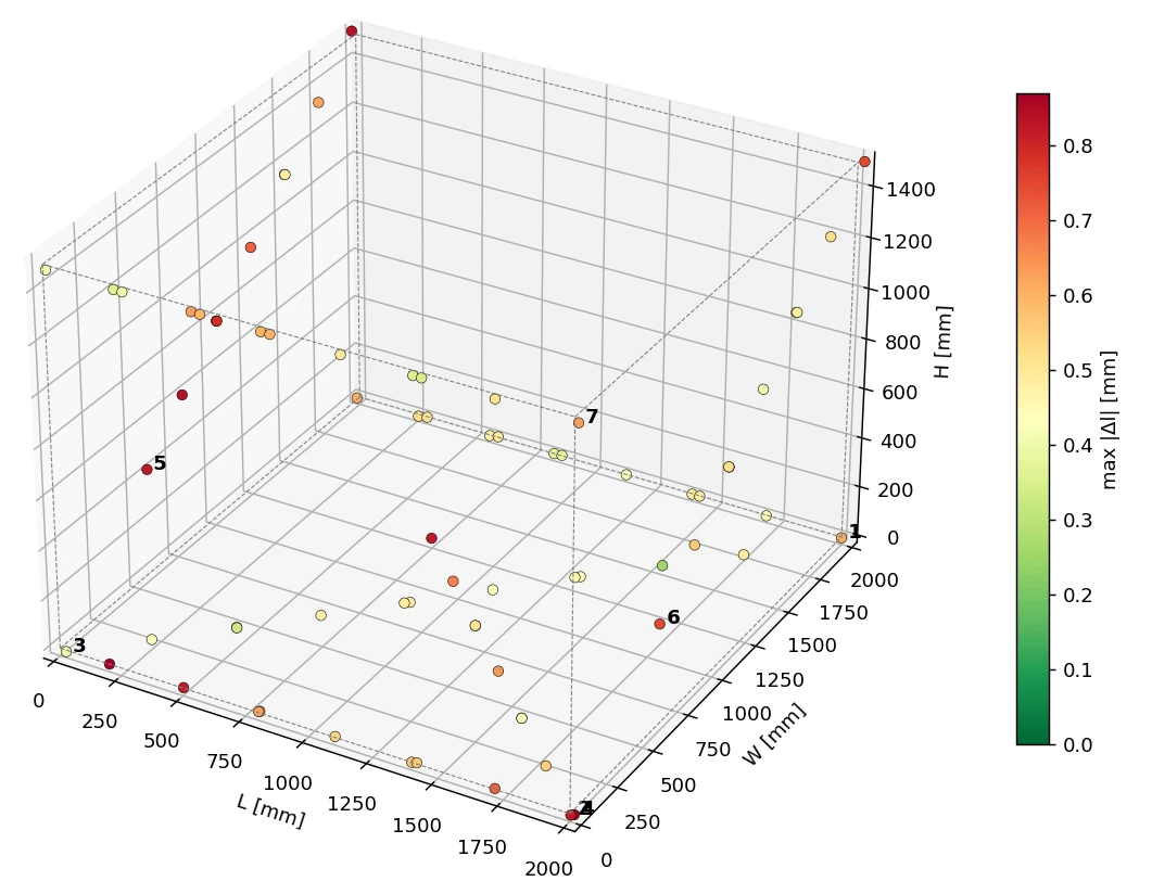
Figure 7: Measurement error determined by (a) |Δl| of sections between neighboring stops and (b) largest |Δl| of all test length ending at each position.
6 Limitations and Deviations from the Guideline
The evaluation follows the method of the guideline, but it does not meet all of its formal requirements. The following table lists the deviations and limitations, together with the reason for each and its effect on the results.
| Item | What was done | Justification | Effect on the result |
|---|---|---|---|
| Artifact calibration | Stop distances measured in-house with a micrometer. There is no calibration certificate. The guideline requires a reference uncertainty below one-fifth of E. With the in-house estimate, this is met for all direct lengths, but not for test lengths above 0.6 m, because the uncertainty of the stop distances adds up over several artifact positions. | The report is product information, not an acceptance test, so the artifact was measured in-house and its uncertainty estimated (see 4.2). The direct lengths, for which the requirement is met, are reported separately in 5.2. | The stated errors include the uncertainty of the reference distances and are not attributable to the system alone. |
| Long reference lengths | Lengths above 600 mm are linked over up to four positions of one artifact. The links are measured by the system under test. | The guideline provides for overlapping artifacts. The link gaps are below 40 mm, so the system only bridges a short distance. | Link uncertainty is at most 0.03 mm. Direct lengths are reported separately. |
| Quality parameter E | E was determined from the measured errors of this test. In an acceptance test, the manufacturer specifies E beforehand and the test verifies it. | The purpose of the report is to document the measured accuracy, not to verify a specification. | E describes this test and is not a guaranteed limit for other installations. |
| Averaging | Each position is the mean of a one-second recording. | Declared operating mode for static measurements. | Single-pose noise is reported in 5.2. |
| Independence | Test performed by the manufacturer. | The report is product information, not an acceptance test. | The results are not independently verified. |
| Orientation | Only the change of the measured orientation over a 600 mm translation was evaluated (see 5.2). | The guideline defines a length-based quality parameter only. The artifact provides no reference for the absolute orientation. | No statement on absolute orientation accuracy. |
| Static measurement | Marker at rest during all recordings. | The guideline tests static probing. | No statement on accuracy during motion. |
| Configuration | One sensor arrangement and one measuring volume. | Smallest configuration for accurate measurement chosen deliberately. | Results do not transfer directly to other setups. |
7 Conclusion and Outlook
With two sensors, the Enpose tracking system measured lengths of up to 2.4 m in a measuring volume of 2000 × 2000 × 1500 mm with a maximum error of 0.87 mm and an RMS error of 0.33 mm. Distances of up to 600 mm were measured with a maximum error of 0.49 mm. The maximum errors of the seven measuring lines were between 0.49 and 0.87 mm. Over a translation of 600 mm, the measured orientation changed by an RMS of 0.38°.
These figures were obtained with two sensors, the smallest configuration intended for accurate measurement. More sensors are expected to improve on them. Evaluations of configurations with more sensors will follow.
References
[1] VDI/VDE 2634 Part 1: Optical 3D measuring systems – Imaging systems with point-by-point probing. VDI/VDE-Gesellschaft Mess- und Automatisierungstechnik (GMA), Düsseldorf, May 2002. Published by Beuth Verlag, Berlin.
[2] ISO 10360-2:2009: Geometrical product specifications (GPS) – Acceptance and reverification tests for coordinate measuring machines (CMM) – Part 2: CMMs used for measuring linear dimensions. International Organization for Standardization, Geneva, 2009.
[3] JCGM 100:2008: Evaluation of measurement data – Guide to the expression of uncertainty in measurement (GUM). Joint Committee for Guides in Metrology, 2008. https://doi.org/10.59161/JCGM100-2008E
[4] Enpose: product website. https://enpose.tech/en/ (accessed October 9, 2026).